Today our featured GD&T term is “features,” which includes “features of size.” But before we jump into this we need to talk about a basic term or thing or maybe we’ll call it a concept, which is the term part. In GD&T a part needs to be thought of as an item, or two or more items joined together, such that their disassembly would cause the impairment or destruction of that thing’s designed use. I think this is important because we in the manufacturing environment labor, discuss and sometimes argue over drawings that have parts on them and those parts are what our GD&T tolerances get applied to. They are the basic unit of our focus and attention. A part is a part.
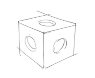
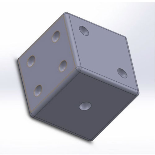
Now parts come in a wide variety of sizes and complexities. But whether they are complex or simple they can be thought of as being composed of things that fit into the above definition of “disassembly causes destruction” which are called features, and from that we get features of size, which are features with distinctions. We can take more steps to break down these features into their more complex constituents, and we will in future posts, but for now we’ll stay here. A feature is defined as being a physical portion of a part such as a surface, hole, boss or slot. A feature of size is defined in the 2009 Y14.5 standard as “one cylindrical or spherical surface (or circular element,) or two opposed parallel elements (or parallel surfaces,) associated with a directly toleranced dimension.” That’s a mouthful but let’s see if we can translate it. Now the first important thing that pops out is “two opposed parallel elements or surfaces.” A cylinder, whether internal or external, fills that bill. The opposing elements on its surface are parallel and they have an associated dimension, which the engineer is required to put on the drawing; so they qualify. Features which are cylinders can be through holes, blind holes, shafts and bosses. A part can have any number of features on it. A planar part has, as the words imply, planes that make up its “wholeness.” A cube is something we easily recognize as a planar part. A typical cube has 6 planar sides. This simple sketch of a cube shows us those planes. For our purposes here we assume it’s solid.  This sketch also shows us how complex things can get in a hurry. Assuming we can see all the features on this part (in other words the sides we can’t see don’t have any other features on them. The features here are 3 holes, to be more precise the holes are blind; they don’t go through the part. So how many features does our cube have now? Did you guess 9? That would be wrong. There are now 12 features that make up our part. 6 planar sides, three cylindrical holes and 3 planar features at the bottom of our 3 holes. Now let’s look at the next sketch. It’s a dice, allowing that in English die is one of a pair of dice but dice is a proper word for both a pair and one dice. Let’s look at our sketch. The part pictured is a cube with rounded corners and it has 3 sides evident with a number of indentations representing the numbers 1, 2 and 4. Let’s assume this dice only has the marks representing numbers on the 3 sides we see. But we can assume that the cube itself is complete as we see it on all the other 6 sides. So it has 6 planar sides and 7 spherical indentations (those representing the 3 numbers we looked at. So how many features does our dice have? 6 planes and 7 cylinders with 7 bottoms like our first example? No, it has 33 features.
  No kidding. It has 6 planar sides, it has 7 spherical indentations, it has 12 radiuses joining all of the planar sides at their corners and it has all 8 spherical corners that meet at the joints of the 3 lines that converge where 3 planar sides meet at 90 degrees, for a total of 33. So we have our definition of features and parts. In GD&T tolerances apply to features as those features relate to parts. GD&T tolerancing controls the shape of features and their orientation to other features. Tolerances control the position and symmetry of features and the relationship of surfaces to the rotational axes of features and parts. And finally, in our digital world, we have controls that tolerance complex surfaces, some of which can only be specified in a computer dataset. This last type makes up what we call tolerances of profile. An airplane wing is an example of a complex surface. There’s one more level that we want to talk about while we’re talking about features. There’s a rule in GD&T that says a tolerance applies to the full width, depth and height of a feature. What does that mean? Let’s look at the dice one more time. We could talk about one of the planar sides and if we applied an orientation tolerance like parallelism to it, as it relates to a plane opposite to it, we could have a viable tolerance responsibility. We’d have to make that cube with two of its sides parallel to a given number expressed in our control. Now for this the tolerance would apply to the full width and height of the plane but not the depth, simply because by definition a plane has no geometric depth. It is a plane. But if we applied that parallelism tolerance to one of the radii that exist at the joint of two of the 6 planar outside surfaces then our definition of the full width, depth and height of our feature can be seen to be valid. The point is that a feature has definition. Features exist where they are defined, in 2 or 3 dimensions and because engineering drawings must have complete definitions for all the things on them then whether our feature is a 2 dimensional plane or a 3 dimensional cylinder, it’s defined size or any tolerance that applies to it must apply to its full width, depth and height.


