In the world of engineering and manufacturing, we say that GD&T gives us the ability to explicitly describe both nominal geometry and its allowable departure or tolerance from that nominal value. One side of the convention allows for the definition of the geometry and the other allows for the definition of tolerance.
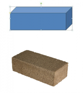
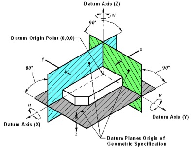
Accomplishing the definitions of both the geometry and tolerancing requires a fairly complex set of rules and procedures which include the very fundamentally indispensable use of datums. Datums provide engineers and countless manufacturing technicians a starting point or reference, fixed on a feature or features of a part, that is used to create and orient the 3-dimensional space in which that part exists. Datums, as we’ve seen with some of our other terms, have different definitions in the perfect world and real world. Datums in the perfect world are defined as perfect things. A datum reference frame is composed of three mutually perpendicular planes, both perfectly perpendicular with each other and each perfectly planar. However when that frame is adapted to a real-world part the story changes. All feature definitions must have applied tolerances and those tolerances always manifest as imperfect features. In the case where a feature is used as a datum, it is called a datum feature. Like some other things we’ve looked at an actual part feature has uniqueness. That uniqueness makes each part, as the term implies, different. I’ll borrow a comparison to say actual part features are like snowflakes, no two are alike. This statement can be argued with because practicality sometimes rules but the truth is that the closer we look, the closer we inspect a real-world feature, the more differences we’ll find. For this reason when a datum is defined by the design or drawing it is one thing and when it becomes a feature on a real-world part it is something else. To prove this point our Y14.5 standard describes the 3, 2, 1 rule. That rule assumes that any real-world part will first need to be landed or fixed in a datum reference frame arrangement in order to measure how that part’s features conform to their requirements. To get an idea of how this is accomplished we need to have a part that gives us a taste of what a real-world part looks like when it’s adapted to a perfect world datum reference frame. So let’s imagine a brick.  This first image shows a drawing of the brick and because it’s presently an idea we can call it perfect. The second image is the real world version of the brick, one that’s made from clay in a crude mold and fired in an oven to make it hard. Now if we want to determine if the real world brick is true to what the engineer wants we have to measure the real world item in a perfect world frame of reference. That means we have to apply the 3, 2, 1 rule to it. First, we take the brick and set it in our datum reference frame and position it so it conforms to the engineer’s needs. See the image below to see a reference frame with a rectangular cube arranged in it.
  The brick’s bottom will be the primary datum A, so we set the brick on the DRF’s perfect A plane and because the brick is really imperfect we learn the brick only comes to a rest on the A plane when it sits on 3 protrusions or points, on its bottom. That’s great because that’s the 3 in our 3, 2, 1 rule. Now, if we look at the picture of our brick we can easily see that it doesn’t form an accurate rectangular cube. The sides on not real planar and they are not square and parallel to each other. So the next thing that needs to happen is the brick needs to scoot on its bottom until it runs into the B plane. Again, because the brick is fairly crude we will only be able to contact that B plane touching two points on the brick’s side, the two high points. Now our brick is sitting in the DRF flat on the A plane and also flat against the B plane, as well as can be accomplished because of the high points on this object. Now our third side of the brick (its end,) needs to lay against the C datum as is then established by scooting the part on its primary datum plane and along its contact with the B datum until it touches the C reference datum plane with what will inevitably be 1 high point of contact. When this has been accomplished the datum features are now said to be located in our datum reference frame. That means we can measure any features on the part as they adhere to the datum reference frame and all the part’s features can be confirmed as to whether they conform to the drawing’s requirements. I think the thing that may be difficult to understand is just how different the real world parts may be from the datum reference frame. Understanding this procedure helps us to establish a methodology for dealing with datum features (real-world features) as the engineer intended those features to be manufactured and measured. Let’s take this one step further and imagine our brick is a part of an assembly with bearing bores and fluid passages and such. We will now be able to take our part, snuggled into its datum reference frame and measure any of its features to whatever tolerance they need to conform to while the part is adapted to the instruments and devices in the measuring lab through the datum reference frame’s perspective.


