Does GD&T Make Things Too Complicated?
I write this blog each month and try to focus on how to convey to our readers what GD&T is and how we can better understand it. There’s always a question about how to apply and use a tolerancing system that is supposed to apply to all the mechanical things we design and build. So, I try to explain the system to those readers, like the many people I meet, who need to use and understand it.
What is GD&T?
GD&T is a complex system of symbols and values designed to give engineers and manufacturers the ability to impart an almost infinite degree of geometric definition to parts while controlling those definitions to an almost limitless degree of tolerance.
The Difference Between GD&T and ISO Standard
I teach the subject to a wide variety of students at local community colleges and area manufacturers, including my employer. Students range from teens to folks in their 60s. So, the approach needs to be flexible while knowing that the world of GD&T has little flexibility. After all, it’s that quality that makes GD&T a world standard. In other parts of the world, it’s called the ISO standard, but the two systems are essentially the same.
GD&T Adapts to Everything That Can Be Designed
GD&T frustrates a lot of people. I’ve had students ask, “If we’ve been making airplanes fly and ships float for decades then why is a complicated system like GD&T needed?” I hesitate to answer a question like that, but in truth, it’s a good one. GD&T is complicated, and it’s evident on the surface that it makes things complicated and more expensive. However, the reason for this system’s complexity is that it’s adaptable to virtually everything that can be designed. From simple to frightfully complex, it can describe features and parts with as much or as little detail as needed, and when used effectively, it’s more cost-efficient.
How GD&T Was Used for Planes in WWII
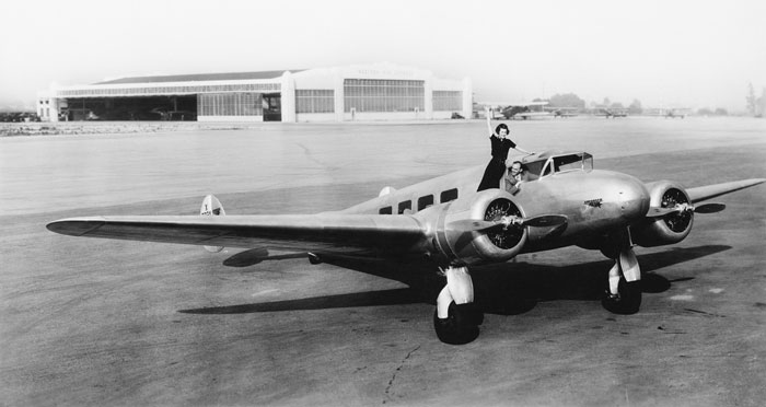
In 1941, during World War II, the Boeing Corporation began rolling 16 B17 bombers off the runway every day in Seattle. Remember those planes with polished aluminum skins and rivets everywhere? Eventually, by the end of the war, those numbers would swell to a total of over 12,000 planes.
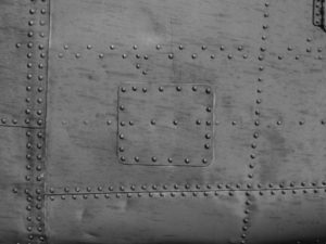
As a side note, I have asked Google more than a few times how many rivets were in a B17. I was never given an answer or even provided a guess about how many there were until a few days ago. I was surfing to find that elusive number when I found an entry by Michael Lombardi, who is a Boeing Historian. After some fair amount of labor, Lombardi put the number at 394,484. He didn’t know what the specific model of the plane that number was accurate for, but I think we can agree that’s a lot of rivets. At 16 planes per day, that amounts to almost 6.5 million rivets. All of these are individually installed by hand on a daily basis.
Boeing’s engineers, mechanics, machinists, and installers accomplished that feat without GD&T. So, why wasn’t that sufficient to avoid the troublesome and costly undertaking known as GD&T? The answer is entwined in the details of what manufacturing was like then and how it has progressed since.
How Designers Use GD&T To Manufacture World-Class Parts
The men and women who design and make parts for things like automobiles, planes, and military weapons have always been tenacious innovators. If a device or part did not function as intended, they’d make changes until it did. Machinists making parts on machines designed to hold thousandths of an inch learned how to coax those machines to far exceed those tolerances. Form, fit, and function were the result of people on our American (and its allies like Britain and France) design and assembly lines making things fit and function. Work was being done off the page so to speak.
Is GD&T a Necessary System for Manufacturers?
So, since this is true, why was there a need to create a system like GD&T? To answer that, I need to explain something very basic; so basic it often gets ignored or passed over. Engineering drawings are pictures. These pictures are conceived and arranged to show and describe mechanical parts with sufficient detail such that almost anyone who is trained to understand what 3.207” means or what 304 CRES is can decode the details of that drawing and reliably let the wheels of their manufacturing world produce that part. Drawings provide pictures with a universally accepted set of instructions.
GD&T in Today’s Manufacturing World
Until our manufacturing worlds accepted and began to rely on the GD&T system to describe the technical specifics of parts, it relied on various dimensioning systems to detail those specifics. Dimensioning systems such as chain, parallel, combined, co-ordinate, and baseline (and there are variants of each) filled in the part-pictures with details of a part’s size and peculiarities. So, was GD&T developed to enable the design of parts that were different than existed before? Looking at this through the eyes of today’s manufacturing world, we can see that some manufactured parts have gotten more complicated and without a doubt the processes that produce them have gotten much more sophisticated, but the parts themselves are not that different.
GD&T Makes Fabricating Complex Parts Much Easier
I have made and seen some very complex parts and assemblies during my time in manufacturing, but those parts do not surpass the beauty and simplicity of the radial engines that kept planes flying during WWII. Watch an animated model of a running Pratt and Whitney radial engine on Google and be amazed at its sophistication.
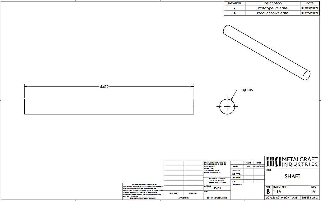
To explain where this is going, I’ll illustrate my words with an example of what we’re discussing. This morning, I received an email with an attached drawing detailing a simple part that a customer submitted an RFQ for (You can see it below).
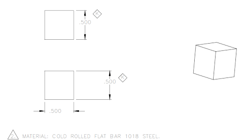
I have redacted all of the customer’s info, but included all the necessary technical info except for tolerancing, which for this part was simply +/-.005” for 3 place decimals, angles held to +/- 1 degree, and a required 125 rms surface finish. The drawing doesn’t specify any adherence to ASME Y14.5. So, if this is important, then why?
GD&T Reduces Manufacturing Times
Let’s look at this simple part. There are not many parts with fewer details, but because of the possibility of geometric variations, this part is more complicated than it appears. What does that mean? When I look at this part, I immediately try to think of a path to manufacture that takes the least time to machine or a method that consumes the least amount of material in its path to the shipping container, moderated by its required volume. Those are valid concerns, but as a manager, I need to first be concerned with a finished product that works when it arrives on the assembly line. Because of the increasingly more diverse and complicated world we live in, the necessity that our part functions properly is far more important.
After a quick look at it, I can think of some versions of this part that will meet the print but will likely not function on the assembly line. The things I am talking about are related to the part’s geometry. So, why do I think I see allowable versions of the part that will not function at assembly? Because the drawing allows versions of the part that are out of tolerance by as much as two to three times the tightest basic tolerance on the drawing. So, you say a part made to the drawing’s tolerances might be two or three magnitudes more inaccurate than the tolerance? No, that’s hogwash! This possibility is, however, true. And we will see why that might be.
Why Cubes Need GD&T
Before we dive into why this might be true, let’s remember that if the part’s design engineer did a proper job of designing this part, then the part that will function properly at a given tolerance will not function properly outside that tolerance, or he would have allowed those dimensions in the first place because looser tolerances generally cost less. That’s proper engineering design. The correct tolerance costs the least, but functions properly.
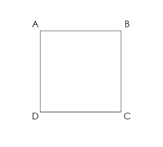
So, let’s look at our cube part again. The sketch below shows the A, B, C and D angles to be square as the drawing shows. Also, the sides are shown equal, making the part a cube per the geometric definition.
 But what if the sides of the cube were not perfectly square, but they were within the tolerance of +/- 1 degree? Let’s say the 90-degree angle (D) in one view was produced at 91 degrees and its corresponding adjacent angle (C) was at 89 degrees. The cube would be a parallelogram (the term rhombus is technically correct) like the one shown below (with opposing angles, both acute and obtuse) being equal and all sides equal and parallel. We could then apply the drawing’s tolerance to any two opposing sides allowing them to be .500” +/- .005”.
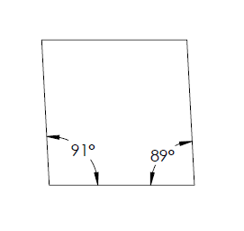 I made this sketch with the angles pictured exaggerated past 91 and 89 degrees, so we could easily recognize the part’s inaccuracies. But let’s agree, for our math’s sake, that the part shown is in angular and linear tolerance.
As our drawing shows, an inspector could measure the cube, one feature at a time, per the tolerances on the drawing, and both the angles and sides would be in tolerance, but the cube’s affected geometry would be outside the limits of its fit in an assembly (Remember, first and foremost the part needs to function).
How GD&T’s Rules Have Changed
Using the verbal description above, the actual fit-up of the block could be oversize by a considerable amount, as we said before (see the sketch below, which is only 1 of its 3 dimensions.) That same inspector might notice that the cube is leaning to one side, as in our sketch, but can he reject it? There is nothing on the drawing that requires it to stand up straight to any value smaller than +/- 1 degree. So, what would be his justification for the rejection? There would be none.
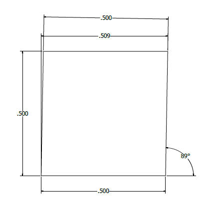
From this sketch, we can see that the envelope of our cube exceeds its 3-place tolerance allowance, but the scope of the drawing does not control that actuality.
So, here we are with the question staring us in the face that asks: Whose responsibility is it? Who says we can’t live with simple? I can hear my father-in-law now, “When I was a boy, my father could fix anything on our tractor any day, anyhow.” When it comes to airplanes and fighter jets and weapons that can fire thousands of rounds per minute, the responsibility for safety and reliability falls on our society’s regulatory authorities. Since my father-in-law’s days, those rules have changed.
Metalcraft’s Next Chapter on GD&T
Stay tuned next chapter for some thoughts on that and more close-up examinations of why GD&T, as technical as it is, serves its social and mechanical responsibilities well.
Thanks, Chris Lindenberger


