Today our definition of terms will focus on “actual local size.” This term refers to a group of values that can be assessed and applied to any feature of size, values that establish the small and sometimes minute irregularities about a feature’s geometry. To understand what this means we first need to go back to a cornerstone of our convention: perfect world / real world. We must acknowledge that GD&T has the job of connecting perfect ideas to real world situations.
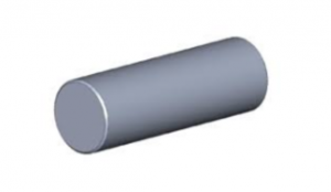 A definition of geometry can have its basis in perfection, such as a cylinder. A cylinder in the perfect world has perfectly straight line elements on its surface, parallel to the cylinder’s axis and at any cross section perpendicular to the cylinder’s axis the resultant section must be perfectly circular. That combination of geometry results in a cylinder. Now while we can have a definition of geometry in the perfect world, we cannot make that definition happen in the real world. That can only be accomplished in the real world using tolerance. Tolerance makes the manifestation of ideas possible in the real world. Without tolerance these things cannot happen. GD&T provides a language that allows engineers to state the conditions of geometry they require, to any degree of accuracy they need, except to a perfect degree. No one has ever released a drawing that said make this feature cylindrical to a tolerance of zero (0.) And they haven’t because it’s impossible. Staying within the confines of our manufacturing rules makes any definition of form, fit and function changeable under the influence of the laws of physics. Hence we need tolerance to provide the wiggle room to accomplish our jobs. Our perfect cylinder in real life actually looks like the graphic below. The closer we look the more imperfections are revealed.
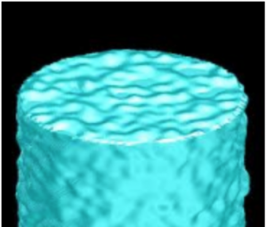
Having said this we can now talk about what “actual local size” means. Let’s imagine a machinist is given a drawing. The part on this drawing shows a cylinder 10.00” long, 1.25” in diameter and its material is specified as low carbon steel. The title block on the drawing identifies the 2 place decimal tolerance to be +/-.03”. So since we don’t see any feature control frames or characteristic symbols on our drawing can we say it’s actually a GD&T drawing? By virtue of the ASME Y14.5 standard note, even without geometric identifiers it is controlled by the fundamental rules of our system. Our machinist appreciates the value of his time so he figures the shortest path to make this part to print is using A36, hot rolled steel bar. He knows this bar will meet the specs for size and finish without needing to turn the OD on his lathe, so he knows he can saw the piece off and face the ends to length and put the finished part and work order on the parts bench and move on to the next job. He might saw his blank from a bar like this:
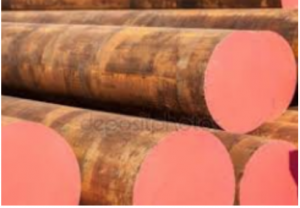
Let’s imagine what this part looks like under close scrutiny. Anyone who is familiar with mass produced steel bar can tell you that hot rolled stock is fairly rough and although diameter tolerances vary by manufacturer, a published tolerance for this 1.25” bar was found to be +/-.011”. As we can see our machinist made a good choice for this job but let’s take a closer look. GD&T applies a complete set of rules to the parts and features it controls. The rules are thorough so that parts will conform to any circumstance of tolerance. We can look at this hot rolled cylinder specifically to see what the “actual local size” criteria impose on its geometry. Actual local size refers to the condition of a part or feature where all of its high and low surface points have been assessed. In the case of our cylinder, if we used a point or blade micrometer and measured our hot rolled bar in hundreds of places around and along its surface we would find a set of numbers that reflected all the high and low points of its rough and relatively imprecise surface. This set of numbers represents the real value of the cylinder’s actual local size range.

I’ve had students comment, “isn’t this taking things to an extreme?” when studying this and similar aspects of GD&T. My response usually sounds something like, “how right does our mechanical world need to be?” GD&T is meant to describe a very precise set of conditions. Parts that find their way into Boeing 787 landing gear assemblies deserve this degree of scrutiny. The engineers that design and detail these pieces of hardware are tasked with the job of making sure their parts will fit and function under extreme conditions. So if we look at those parts in this extreme light we can see that they are exactly what they need to be and we can prove it. The consequence of this level of scrutiny is a guarantee that the millions of lives ferried to their destinations aboard our 787 will arrive as they were intended, thanks in part to actual local size.

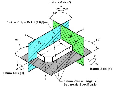
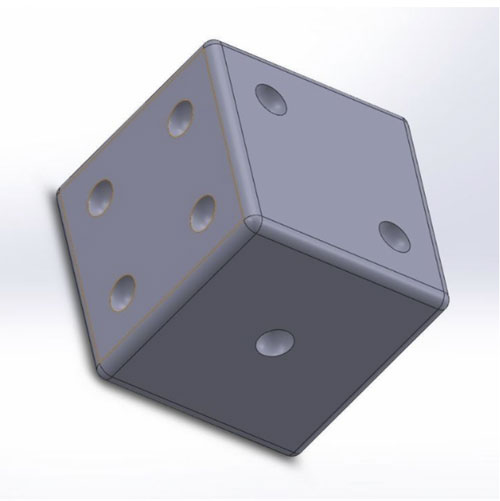
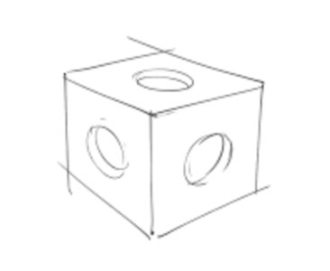 This sketch also shows us how complex things can get in a hurry. Assuming we can see all the features on this part (in other words the sides we can’t see don’t have any other features on them. The features here are 3 holes, to be more precise the holes are blind; they don’t go through the part. So how many features does our cube have now? Did you guess 9? That would be wrong. There are now 12 features that make up our part. 6 planar sides, three cylindrical holes and 3 planar features at the bottom of our 3 holes. Now let’s look at the next sketch. It’s a dice, allowing that in English die is one of a pair of dice but dice is a proper word for both a pair and one dice. Let’s look at our sketch. The part pictured is a cube with rounded corners and it has 3 sides evident with a number of indentations representing the numbers 1, 2 and 4. Let’s assume this dice only has the marks representing numbers on the 3 sides we see. But we can assume that the cube itself is complete as we see it on all the other 6 sides. So it has 6 planar sides and 7 spherical indentations (those representing the 3 numbers we looked at. So how many features does our dice have? 6 planes and 7 cylinders with 7 bottoms like our first example? No, it has 33 features.