In today’s installment I want to talk about the language of GD&T and perhaps a little about basic geometry and how shapes fuel our thoughts. Any language, to achieve communication, must somehow capture a physical method, accomplishable by our bodies, to change a thought or imagined image, into a physical presentation of some kind.
Put in simpler terms, we have a thought and we find a way to present that thought outside our minds. The process is complicated because for any kind of system that performs this transformation of an intangible “thought” to a tangible communication there is a need for a system that can be digested and understood by a wider audience. That system needs a sophisticated population of tools that by their uniqueness can each evoke a volume of thoughts and images and by their amalgamation can assemble libraries of schemes and constructs. GD&T gives our engineering / manufacturing world that diversity of capability. Let’s go back to grade school, back to when we learned about how our world contained things like mathematics and geometry and scientifically logical conclusions. We learned that ideas like points and lines and planes weren’t just thoughts but actual pieces of a puzzle that when assembled became a warehouse full of ideas and images in which we could store our newly empowered imaginations. Triangles and cubes and solids of various shapes allowed us to see our world in a new light. Mathematics and geometry gave our vision a new depth. With this education came the ability to see and perhaps ‘understand’ some of the components of our observable world.
A world filled with geometry
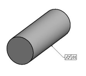 An example of what I mean is a cylinder. A cylinder is a simple looking object that by virtue of its useful uniqueness can be found in virtually every corner of our lives. Broomsticks, coffee cups, hotdogs, ball point pens and tootsie Rolls all comprise a diverse array of things that we can see without even needing to turn our heads. The simple cylinder is actually not so simple though. If we take a brief look at its geometry, its mathematical structure, we can see that it is composed of a number of geometric principals, all with some fairly complicated interrelationships. A cylinder, in the world of ideas, is made up of an assembly of lines, arranged in parallel and at a common distance from an axis, (another geometric principal,) all arranged to be congruent with circular elements, perpendicular to that axis at any point along its length. This solid can occupy as much or as little space as can be imagined. Now we have taken this diversion of our attention to illustrate our discussion on the needs of language. This simple cylinder, which is not so simple, presents a demand requirement on our ability of giving communicable definition to shape, mathematical logic, size, volume and the perhaps an infinite number of things that may cause one cylinder to differ from another. Our cylinder needs to exist both in the perfect world of ideas and then find its way into the real world of our manufacturing plants and shops where nothing happens without agreed upon tolerances that govern form, fit and function. And so we have our cylinder, shown here with a simple callout controlling cylindrical form, and with that one symbol we exert straightness, roundness and coaxiality on its surface elements. The envelope principle of perfect form at MMC is enforced as it enters the real world of tolerances… GD&T speaks a unique language that only a specially trained group of people can appreciate. With a simple symbol by the name of cylindricity, accompanied by a system of applied value using an arrangement of tools like characteristic symbols, modifying symbols, feature control frames, tolerance zones and the many ways to mathematically define and translate these bits and pieces into statements and paragraphs of geometric definition we can communicate a sufficient wealth of data to replace untold pages of written text about our broomstick or coffee cup with a few carefully arranged numbers, symbols and organized compartments. Our language can consolidate time and energy into a form that speaks to the uniquely educated inhabitants of our increasingly diversified manufacturing world and it accomplishes the task with remarkable specificity. Each GD&T engineering statement can be crafted to define any assemblage of shape and function. At the same time it describes this intricate physical relativity that same statement can define to any finite degree a scheme of tolerance that will make the assemblage accomplishable in some real world situation. GD&T is the ultimate tool for describing mankind’s present reality and future.
The alphabet of GD&T
So let’s take a look at the alphabet of our GD&T language. At the heart of GD&T we have the jewels of the system, which are the 14 characteristic symbols. Most of us are familiar with and understand these to be the geometric controls of the system. They include form controls like circularity and flatness,![]() . These symbols define shape, irrespective of relationship to other features. A circle and plane have geometric definition. Others are symbols such as parallelism and angularity,
. These symbols define shape, irrespective of relationship to other features. A circle and plane have geometric definition. Others are symbols such as parallelism and angularity, ![]() , which are used to control the relationship of parts and features, also mathematically definable. The 14 characteristic symbols have 5 definable types, which are form and orientation, such as the ones above and position,
, which are used to control the relationship of parts and features, also mathematically definable. The 14 characteristic symbols have 5 definable types, which are form and orientation, such as the ones above and position, ![]() , which allows the specific placement of features with respect to other parts and features. There are runout controls,
, which allows the specific placement of features with respect to other parts and features. There are runout controls, ![]() . These controls define the size and or extent of allowable surface movement of planes and cylinders to axes of rotation, which define a kind of dynamic relationship of features. The last type of characteristic control is known as profile,
. These controls define the size and or extent of allowable surface movement of planes and cylinders to axes of rotation, which define a kind of dynamic relationship of features. The last type of characteristic control is known as profile, ![]() . Profile is a flexible shape and relationship control. Our modern design facilities are powered by computers configured to aid designers with the super-fast and intricate capabilities of three dimensional computer modeling. Imagine designing and drawing a jumbo jet’s fuselage, detailed on a desktop screen smaller than the windshield of a subcompact automobile, in complete detail. It can be stored in an instant and recalled in a keystroke. The shape, as intricate as it needs to be to carry a million pounds through the air at near mach speed is stored in a computer data file. These profile controls use the definitions saved in those files and give engineers a virtually infinite choice of definable shapes to employ.
. Profile is a flexible shape and relationship control. Our modern design facilities are powered by computers configured to aid designers with the super-fast and intricate capabilities of three dimensional computer modeling. Imagine designing and drawing a jumbo jet’s fuselage, detailed on a desktop screen smaller than the windshield of a subcompact automobile, in complete detail. It can be stored in an instant and recalled in a keystroke. The shape, as intricate as it needs to be to carry a million pounds through the air at near mach speed is stored in a computer data file. These profile controls use the definitions saved in those files and give engineers a virtually infinite choice of definable shapes to employ.
Characteristic controls
So as we see, at the heart of the system are the 14 controls, straightness, flatness, circularity, cylindricity, which are the form controls. There are the orientation controls, which are parallelism, perpendicularity and angularity. We have position controls: position, concentricity and symmetry and runout controls, both circular and total. Last we have profile controls. They are profile of a line and profile of a surface. As I mentioned many of us are at least somewhat familiar with these tolerances. However, those that need a brush up or a more in depth familiarization of these things can easily find ample material to study on their browser of choice. This installment has, I hope, given us the opportunity to see the need for a method of communication, written on the backdrop of our system fundamentals, that speaks an abbreviated but fully intricate language of engineering definition. Next time we’ll look at how we use the tools like our characteristic symbols to write sentences that craft geometry into form and establish relationships that accomplish mechanical function. Readers that may want to look ahead can review terms like datums and constraint and the concepts that guide their use. We’ll be looking at feature control frames and how they’re used to make engineering statements using the tools we’re studying. We’ll look at various kinds of symbols and how they’re used to make brief notes in place of longer and often tiresome text notes. We’ll look at the numerous ways drawings have used and defined styles of tolerance over the years to learn how we can now be more specific and accurate. After we learn the bits and pieces, and after we learn how those pieces assemble to form our language, we’ll begin to look at tolerance zones. Tolerance zones comprise the glue that holds our system together. Tolerance zones are not only the embodiment of values for our system, they’re the arrangement of those values and how they control shape and relationships. I hope this material brings into focus some of the things our readers told us were fuzzy in their minds. GD&T is complicated but it is elegant in its intricacies once a person begins to arrange its pieces into an organized structure. We encourage comments and questions and will continue our efforts to fill these spaces with meaningful information. We’ll talk to you next time.


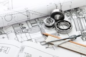
 It’s a language, much like Spanish or English. It uses symbols, like our English symbolic alphabet, to represent an object, function or process. The need for a symbolic method of conveying ideas and function on engineering drawings can be easily understood if a person tries to imagine how they might describe a carburetor in words sufficient to allow a machinist to make one out of a block of aluminum. Pictures and symbols are worth a thousand words, and many more, so our engineering drawings give us access to tremendous caches of information in incredibly abbreviated forms, abbreviated but precise and detailed.
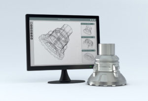
 After all, GD&T is not like coordinate or baseline tolerancing methods. It’s a whole new animal and we’re in a whole new era. It’s a complicated system of geometric symbology – a system that can describe, to any degree, the limits of form, fit, and function of an infinite set of physical circumstances. But it’s not an intuitive system. GD&T is all about rules and defined symbols with specific translations. GD&T is “do it right or don’t do it.” It requires critical thinking skills to question drawing interpretations, before, during, and after parts make it through our shops and quality departments. Starting with this blog, we hope to kick off a vigorous discussion about the implications of GD&T so that we all not only get a better feel for the system but can work together to promote its best and consistent use in our industry. In upcoming blogs in this series, let’s collaborate to shed light on some of these problems and solutions. Specifically:
