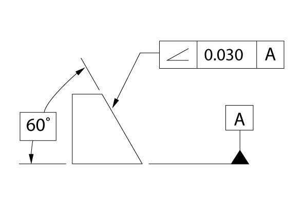
In GD&T basic dimensions used to be a fairly simple thing to define. However, today, among other things, “Basic dimensions” are numbers on an engineering drawing that represent values of size in whatever the measurement system being used on the drawing is. Those values are used to describe the theoretically exact size, profile, orientation or location of a feature or datum target. Those values can be recognized as “basic dimensions” because they are identified by the fact that they’re contained in a box drawn with a thin solid line.
Basic dimensions, identified by the engineer, locate tolerance zones. Because that’s true, basic dimensions identify tolerance information located in feature control frames that state geometric tolerances. When an engineer makes a statement of tolerance, that statement is made in the form of a feature control frame. Feature control frames have an defined format in the ASME Y14.5 standards, which can be found elsewhere in this glossary. It can be said that Basic dimensions were identified by the engineer to eliminate possible confusion resulting from which dimensions would or should be used to establish the tolerance contained in the feature control frame. We can see in the illustration below that there is an angularity tolerance stated to control the angled surface that the feature control frame points to. It states a tolerance of .030 units to datum A. We can also see that the toleranced surface and the datum A surface have extension lines leading to a value listed inside a box stated as 60 degrees. So we see in this very simple drawing all the ingredients for our tolerance. We have a tolerance type, a tolerance value and when we look for our basic dimension we see the identified 60 degree value inside the box, which is our basic dimension. 

However, today, due to the advent of CAD based models that control part geometry the industry is seeing some new wrinkles. It’s becoming common, usually with the addition of a note on the drawing, to find that it (the note,) says that for undimensioned features refer to 3D data-file. All dimensions from the file are considered basic and shall be controlled by the tolerance (meaning the applicable geometric tolerance) indicated on the drawing. Drawings with this verbiage, in our experience, contain increasingly less dimensioning on the face of the 2D drawing in keeping with what is known as PDD (partially defined drawing.) This, in our minds, does a good job of defeating the purpose of basic dimensions. GD&T was constructed and developed around the concept that coordinate tolerancing lacked the ability to adequately specify both the geometry and tolerancing of our mechanical world. GD&T gives us those capabilities. But PDDs may be causing problems with GD&T’s ability to be precisely specific. I’m looking at a customer’s drawing. That customer is a government prime contractor. The drawing I’m looking at portrays a part that serves as a mounting plate, with more than 50 various size holes that are tapped in a number of sizes, or reamed for hardware installation etc. The part also has a number of cutouts that may be lightening features and some that likely serve to mount specialty assemblies or hardware. There are 14 GD&T feature control frames on the drawing. There are a total of 5 coordinate tolerances on the drawing, and two reference dimensions. Except for the written notes that’s it. Not one dimension inside our defined boxes. The note I mentioned earlier, about undimensioned features is meant to absolve the company and its engineers from giving us the data that our ASME standard promised. I’m sure there are arguments to justify why companies are doing this but in our mind those arguments only support a value to the originator of the drawings. It saves time and makes their drawings more concise, which are good things for them. But that note doesn’t do away with why the standards defined and implemented basic dimensions in the first place. They define the exact size, profile, orientation and location of features.


