This month’s installment of our definition of terms will be about characteristic symbols. These symbols are what most people in the manufacturing world recognize as being what GD&T is all about and, from one perspective that’s true.
Those Weird Hieroglyphic-Looking Things
When the average worker in our manufacturing world first sees an example of GD&T, it is likely they find it on a drawing. It’s much like the other drawings they’ve learned to interpret, only this one has some weird hieroglyphic-looking things mixed in with the normal lines, arrows, and numbers that they are used to. Upon seeing the hieroglyphics, they might look to their left and right to check if anyone is watching them, then nonchalantly mosey over to their computer to start Googling.
Target Thing = True Position
They might be thinking to themselves: “What the heck is this target-looking thing?” After some scrambling, they will find the “target thing” means “true position.” And so it begins. Our average worker who has entered the world of characteristic symbols now knows the term, true position.
Quality, Quantity, Variety, and Specification
Geometric dimensioning and tolerancing is a system designed and utilized to control, manipulate and enhance geometry. Words like “cylindricity,” “angularity” and “flatness” describe geometric qualities and those characteristic symbols represent a set of values or qualities that cover the extent to which our manufacturing and design world needs to give these things quality, quantity, variety, and specification.
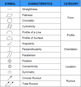
There are 14 characteristic symbols in both our American Y14.5 system and the ISO system used prevalently in Europe and other countries. However, there are still some minor differences in how they are defined and utilized. The definitions in this blog are Y14.5 specific.
14 Symbols in 5 Categories
If we look at the graphic below, we can see that the 14 symbols each have a characteristic definition and they are categorized into five different types. These characteristic definitions and types are arranged so that the features on manufactured parts can be controlled for their shape, angular orientation, location, and dynamic relationships to other features and parts.

Just to keep our terms in perspective, let’s remember from previous posts that a “part” is a collection of features that cannot be disassembled without destroying the purpose or function of its original construction and a “feature” is any physical portion of a part. Features can be, among other things, edges, faces, holes, bosses, slots, cones, and spheres.
A Symbolic Engineering Language
Now, let’s revisit the definition of “GD&T.” GD&T is a symbolic engineering language (as in a system of communication used by a community of people) for defining geometry and communicating tolerance. Symbols are marks or characters used to represent objects functions or processes. In other words, symbols are a way to synopsize a volume of information. Symbols use a small amount of visual data to convey a package of meaning. They are the proverbial pictures worth a thousand words.
So our characteristic symbols give us an approach to the nuts and bolts of geometry. If something needs to be flat, there is a symbol for that. Its definition is specific for that characteristic, both in the way it applies the definition of perfect geometric form to real-world features and where it applies them. It also conveys in what proportions it applies tolerance to every conceivable possibility we engineers can imagine.
Introduction to Characteristic Symbols
So, we have these 14 symbols to learn about and, as a part of this introduction to the characteristic symbols, I will start with one of them and try to establish a format that we can follow as we go through them. As I said before, each symbol has a definition of what it controls and each symbol will also fall into one of five categories.
Flatness
The first symbol we’ll study will be flatness. Flatness is a form control. Form controls are about shape and uniformity. Shape is shape. We relate to shape in the things we see. Balls, tree trunks, hot dogs and parking lots show us shape and we relate to shape when we learn to differentiate between things.
Uniformity
Uniformity is about consistency and conformity. It gives us more information to distinguish physical quality. How round is the ball? How flat is the parking lot? So our first characteristic deals with form and we’ll learn how to define how it’s used through how uniform any example of its use is required to be.
Planarity
Flatness is also planarity. Planarity, in geometry, is any surface in space of which two points are chosen (any two) and when these points are connected by a line, the line will be entirely in the plane surface.
Flatness, in engineering terms, is any surface (of points) in 3D (X, Y and Z) space that exists entirely in two of those dimensions, such as X and Y, but not in the third (Z).
Flatness Tolerance
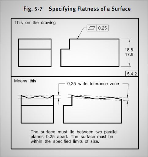
The flatness tolerance can be applied to any surface by attaching the tolerance to the extents of it and applying a tolerance or definition of its allowable imperfection. That imperfection will be stated as a value of distance or space lying between two parallel, theoretically perfect, planes disposed about the plane in question (see the next graphic taken from the ASME Y14.5-2009 standard.)

Our example shows a perfect part designed to be constructed as in the upper frame. Then, it shows what it can look like with allowable imperfections in the second frame.
Our flatness tolerance is a form tolerance, one of four characteristic symbols that belong to the form tolerances. Since the shape of something can be defined as a standalone value form tolerances do not require datums in their feature control frames.
The flatness tolerance may be applied to either features or features of size. When it’s applied to a surface the evaluation is made of the space between the two parallel planes as shown earlier.
Regardless of Feature Size
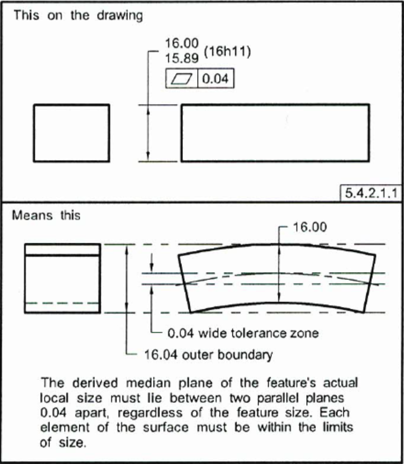
When it’s applied to a feature of size, it may be applied at RFS (regardless of feature size) in which case the tolerance zone is two parallel planes disposed about a derived median plane assembled from the midpoints of the parts actual local size geometry and the outer boundary must be equal to or less than the part’s high size tolerance plus the flatness tolerance. (See graphic below from the ASME Y14.5-2009 standard.)

Maximum Material Condition
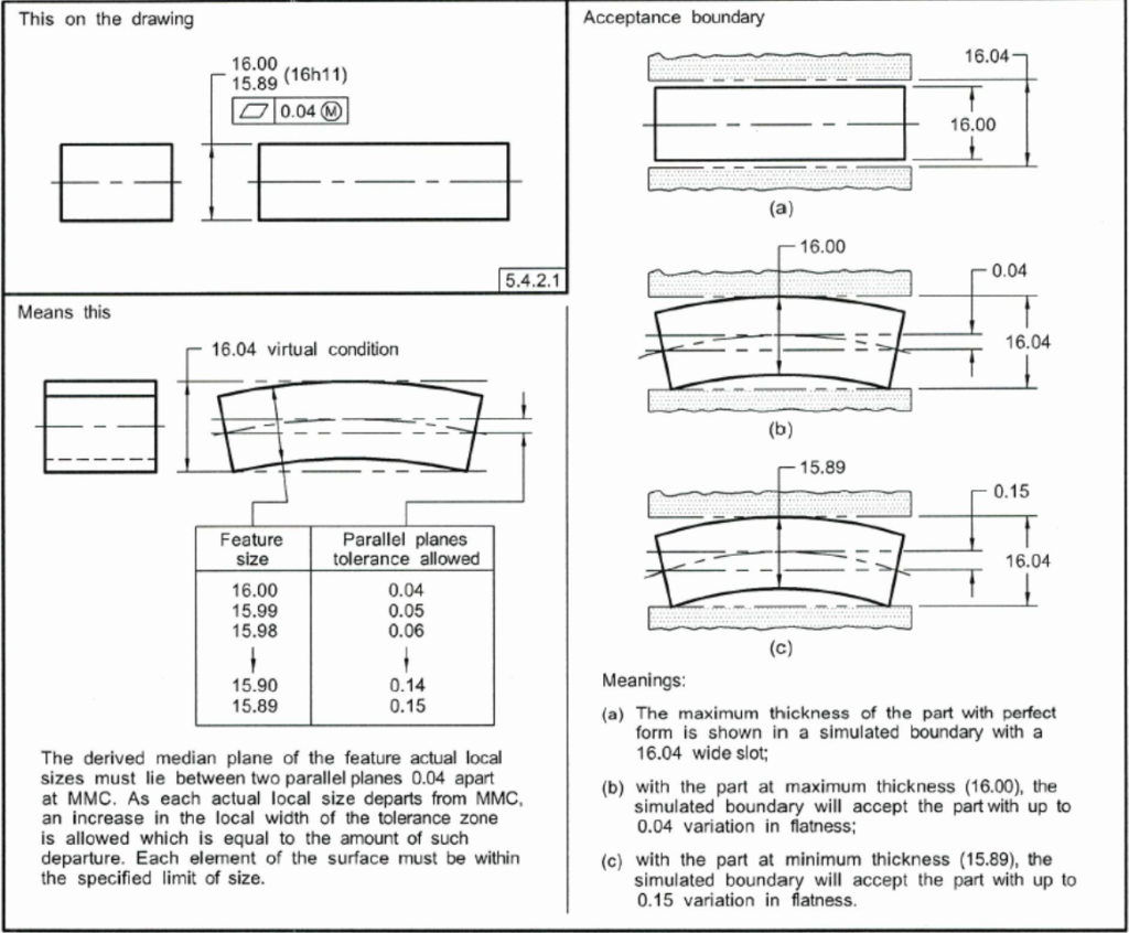
Flatness can also be applied to a feature of size at MMC (maximum material condition) in which case the tolerance is assessed using the surface condition or virtual condition of the effects of the tolerance. The method uses a fixed gauge which allows for the combined value of the flatness tolerance added to the size of the feature at MMC. (See graphic below from the ASME Y14.5-2009 standard.)

In future posts, we will examine the remaining form tolerances and move on to the orientation, location, profile, and runout tolerances.


