In our last blog post, we looked at the six common tolerance zones that appear in today’s engineering drawings. While these six make up the broad majority of tolerance zones in geometric dimensioning and tolerancing (GD&T), you may encounter another zone in a given tolerance scheme—the spherical tolerance zone.

The American Society of Mechanical Engineers (ASME) Y 14.5-2009 standard, paragraph 7.4.6, outlines the use of location tolerancing with spherical diameters stating that a spherical diameter symbol precedes both the feature and the positional tolerance value (shown in fig. 7-35 on page 127 of the standard.)
A spherical diameter feature’s center is identified with a point, which engineers can use as a datum or simply the location of a part feature. The illustration below depicts a 2” diameter spherical feature called out as a spherical diameter with a positional tolerance imposed to datums D and P.
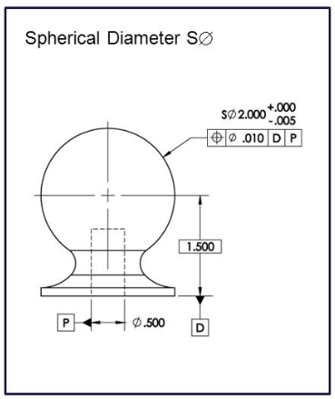
Source: University of Florida
The example below shows a part with a spherical feature with its location controlled by the feature control frame to a .2 mm spherical diameter tolerance zone at least material condition.
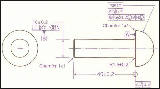
Source: University of Florida

Additionally, this example shows the feature itself identified in what may be a basic dimension box and the dimension locating the spherical radius of the feature is shown as 40mm with an applied distance tolerance, which may interfere with the geometric position frame.
The Y 14.5 standard also explains that a sphere’s location can be controlled with other than a spherical diameter zone if the spherical feature needs to be located in a bidirectional zone (shown in Fig. 7-28 on page 124 of the standard.)
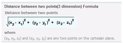
You can use the same formula for regular feature locations as you can to solve positions involving spheres, holes, and bosses, only using 3 deviations to sum the squares instead of 2, such as in this formula: 2* √(A2+B2+C2).
According to David Slopsema, head of Dimensional Consulting,
“You just need to find the true distance between the actual position of the feature and the true position. That distance must be smaller than the radius of the spherical tolerance zone.”
Source: David Slopsema
You may notice the formula above is missing the 2X multiplier, but Slopsema’s comment about the radius of the spherical tolerance zone explains its interpretation to be half of the diameter zone.
Slopsema also wrote Dimensional Consulting’s Free Online GD&T textbook. This entertaining is very easy to understand and we recommend it to anyone looking to learn more about GD&T.