GD&T is a convention that gives the engineering world a tool that enables designed components to have both an unlimited variety of both geometric definition and tolerance. Consequently GD&T is about many things but it is ultimately about the disposition and appraisal of tolerance zones.
This month our definition of terms will be about tolerance zones: what types there are, how they’re arranged and the different ways engineers give them value.
We can get started with the zone called “2 parallel planes.” I’m beginning with this because it’s a very basic zone and is used as the default for many tolerances.
We can see a graphic depiction of it here.
2 parallel planes describe the volume of space used to control things like the orientation of planar surfaces (angularity and perpendicularity etc.) It can also be used to control form, as in flatness or symmetry, as in the location of a planar feature like a slot or a rectangular boss. The runout tolerance uses parallel planes to control dynamic feature tolerance situations, which manifest as the wobble of planar surfaces perpendicular to axes of rotation.
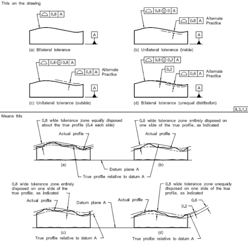
There is also a version of 2 parallel planes used for complex features like the shape of an airplane wing or a complex cam surface as shown below.

The 2009 Y14.5 standard expanded the allowable arrangement of this tolerance zone to include values disposed on part profiles either on the inside or outside or any combination of both, as shown below.
This version of the 2 parallel planes tolerance zone (used in the surface profile tolerance) is considered to be the most powerful of all the characteristic controls in that it can be used to simultaneously control size, form, orientation and location in one control.
The 2009 standard also gives engineers the ability to change the values of the zone in non-uniform ways to create an almost infinite variety of shapes and conditions.
Now, we’ll look at our next zone which is a cylinder. A cylinder is also a common tolerance zone in GD&T. The volume inside a cylinder is used to define the allowable deviations of the axes of features of size like holes and cylinders and cones.
These zones are used to control location, orientation, and the extent of derived median lines used in concentricity and straightness.
The first look at this zone is like the following graphic, which shows a cylindrical part with a tolerance zone for its datum axis and a cylindrical feature axis as it deviates in its allowable “cylinder” of volume.
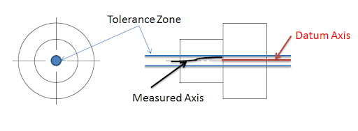
The cylinder is used to apply a tolerance zone to location tolerances and the volume inside the cylinder becomes the area that the axis of the feature is allowed to roam while remaining in tolerance.
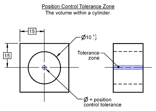
The graphic above shows an internal feature of size with a cylindrical tolerance zone applied to control its location, shown as the 3 dimensional purple zone in which the hole’s axis must remain.
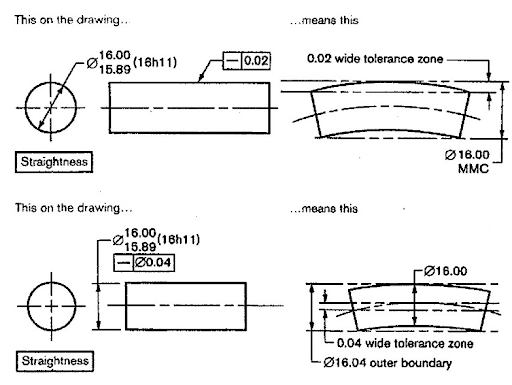
Our next tolerance zone is called 2 parallel lines. This zone controls two dimensional elements in straightness applications. These controls are limited to the surfaces of cylinders and flat surfaces or derived median planes. The control of flat surfaces is limited to lines parallel to the longitude of the profile view of the callout as shown below.
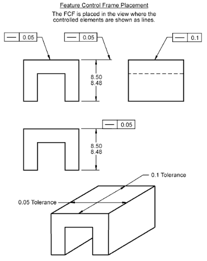
The control of the straightness of cylindrical elements is done by controlling either surface elements of the cylinder or by controlling the axis of the feature of size as shown in the graphic below; note the diameter symbol in the control frame of the second example.
Our next zone will be coaxial circles. There are several controls that use circles for tolerance zones. This type of zone is for surfaces and is 2-dimensional. Circularity, runout and possibly profile are controls that use this type of zone. There are two versions of this zone, one of which can only be used in runout.
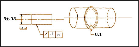
The first type of coaxial circles tolerance zone is used in the circularity and runout controls and is identified as coaxial circles offset radially. They can be disposed on a cylinder, along its axis and control the specified zone of circularity or runout for a 2-dimensional cross section of the cylinder at any point along its length.
The graphic below shows a cylinder toleranced with circular runout to .1 mm and illustrates the .1 mm tolerance zone after taking a cross section, perpendicular to its axis, through the surface of it. This shows the coaxial circles offset radially.
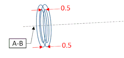
The next graphic shows the axis of datum A-B with two sets of coaxial circles offset axially along that datum, spaced at a .5 mm tolerance. These circles would represent tolerance zones for circular runout taken at two locations on a plane perpendicular to the axis of rotation of A-B.
The last zone in our discussion is known as 2 coaxial cylinders. It’s a common zone used in form, profile and runout controls. This zone is also a surface control and limits the deviations of controlled surfaces to lie within the specified value needed for the application such as is pictured in the graphic below, shown in grey.

So to recap, we have looked at the following 6 zones.
1) two parallel planes.
2) the cylinder.
3) two parallel lines.
4) two coaxial circles, both offset radially and axially.
And 5) two coaxial cylinders.


