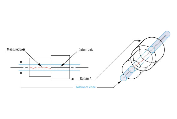
Today we’re going to look at the concentricity control. This control is used a lot in a variety of situations that involve coaxial relationships. The definition states that concentricity controls ‘all’ diametrically opposed elements of a figure of revolution.

Breaking Down the Basics
Let’s break that down and look at a few rules for this tolerance. First we have the term ‘diametrically opposed.’ In geometry this means exactly opposite on a diameter. Next we have the word elements. This refers to an entity that satisfies all the conditions of being in a set. In our case this set contains all the lines that intersect both the diameter and the axis of the cylinder in question, when those elements are normal or square to that axis. Each element is a line that passes through the opposite sides of a cylinder and through and perpendicular to the axis of the cylinder. On an imperfect cylinder, which includes all the cylinders in our manufacturing world these elements run from one side of the cylinder to the other and because the inside (or outside, because each is simply a surface,) of our cylinder is imperfect each element will touch imperfections on both sides of that surface so when the axis of the cylinder divides the element in two, the two parts will be unequal.
Using Elements To Divide An Imperfect Cylinder
If we can imagine inscribing even a moderate number of these elements inside our cylinder it’s not too difficult to imagine a bunch of dividing points on our line elements and because they are each located at a different place inside our imperfect cylinder the points that divide them will definitely not be lined up, in fact they will appear to be what is described as a cloud of points. Our cloud of points is made up of the bisections of all those diametral elements. And when our cloud is associated to a concentricity tolerance, such as we’re working to define, that cloud must lie inside a cylinder equal to the value of the tolerance in the FCF. I’ve seen this cloud referred to as a derived median line but it’s really a derived solid, imperfect cylinder.
Foundational Knowledge of Concentricity
Concentricity is also allowed where we have two or more radially disposed features about a datum axis such as hex features and other like geometry. Concentricity must reference a datum to be a valid control. That datum is always the axis or point of rotation of the datum feature. It is also OK to reference two datums, one primary and one as the datum axis, in cases where a flange or hub feature attaches to a rotating member and the hub face must be acceptably perpendicular to the datum axis as well as coaxial. Concentricity is always to be taken at RFS. No material condition modifiers or datum feature modifiers such MMC or MMB are used with this control. The tolerance zone is always cylindrical and coaxial to the datum axis or spherical and coaxial to the datum center point. Controlled features are usually cylindrical but can be spherical and I’ve seen conical features included in the definition but that may be OK because a cone can be looked at as an extremely imperfect cylinder.  So here we have a concentricity callout in our FCF. It states that the feature in question must be concentric to datum A to a tolerance of .001”. That’s pretty much a typical callout. I took it right off of a drawing I quoted last week. Now we can step back and assess what we’ve described. For the most part we have a feature of size that’s been chosen to have a close relationship to some other feature’s datum axis. To make an assessment of whether the part conforms to our concentricity callout we must make a representative check of the surface of our controlled cylinder as it compares, by our definition, to the datum axis. To accomplish the task we must make a considerably large number of measurements. We would need to determine if our bisected, diametrically opposed elements, describe a cloud of points that all fall within our tolerance zone cylinder. Not only is that a mouthful but it’s a sizable measuring job.
Justifying The Use Of Concentricity
Here we get to a place where there are a number of opinions flying about our GD&T user world. “To use or not to use concentricity, that is the question.” My cut at it is, “Don’t, unless you need to.” Coaxiality can be achieved in GD&T using several methods. Position accomplishes it and so does runout. So why might we not use concentricity could be explained with the above definition of the complexity of the tolerance. Why we would use it should probably boil down to if we really need it. There’s a consensus of expert opinion that the possible real need for concentricity would be in cases where there is a high speed rotating mass or perhaps a need for extreme balance in a coaxial relationship. Concentricity does provide a close distribution of coaxial mass, which would lend a needed quality of balanced mass and inertia. So in cases where these qualities are needed, the onerous task of proving concentricity would be justified. However, for the task of achieving simple coaxiality, position or runout can be used where the axes of the datum and toleranced feature can be measured by finding the actual mating envelope of the feature or simply putting an indicator on a rotating assembly. I think the long history of using concentricity to achieve coaxiality is no longer needed. It’s interesting that concentricity has been used on coordinate toleranced drawings for a long time, long before the prevalent use of GD&T, and maybe that’s the reason why we still see it used as much as we do.


